 International
 Singapore
 Malaysia
 Thailand
 Vietnam
Your shopping cart is empty!

DIY Digital Alarm Clock Using REKA:BIT With Micro:bit | Tutorial for Beginners
- Abdulrahman Alhamed
- 22 Oct 2021
- 857
LCDs are very popular and useful when you need to display some information like sensors data from your project, and once it comes to use it with REKA:BIT it couldn't be easier. So let’s build a digital alarm with LCD and potentiometers.
Video Tutorial
Step 1: Components and Tools
- 1x REKA:BIT board with micro:bit v2
- 1x 3V3 I2C 1602 Serial Character LCD
- 2x Potential Meter 10K
- 3x Grove to female cable
- 1x Battery Holder
- 4x Cable ties
- 1x Box
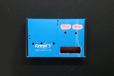
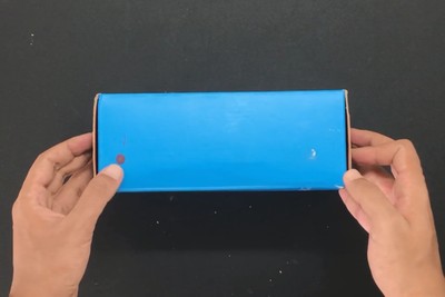
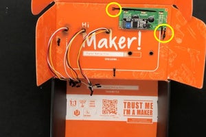
Step 2: Make Alarm Box
Grab the box and make holes in it as shown in the figures below:
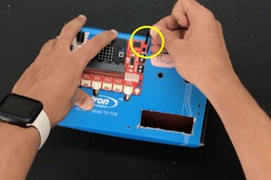
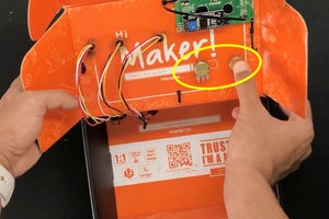
Step 3: Attach Components to the Box
By following the figures below:
- Fix REKA:BIT and LCD in the box using cable ties
- The potentiometer should be inserted above the LCD
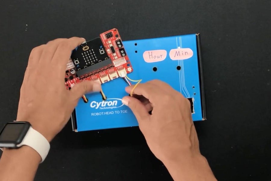
Step 4: Connection
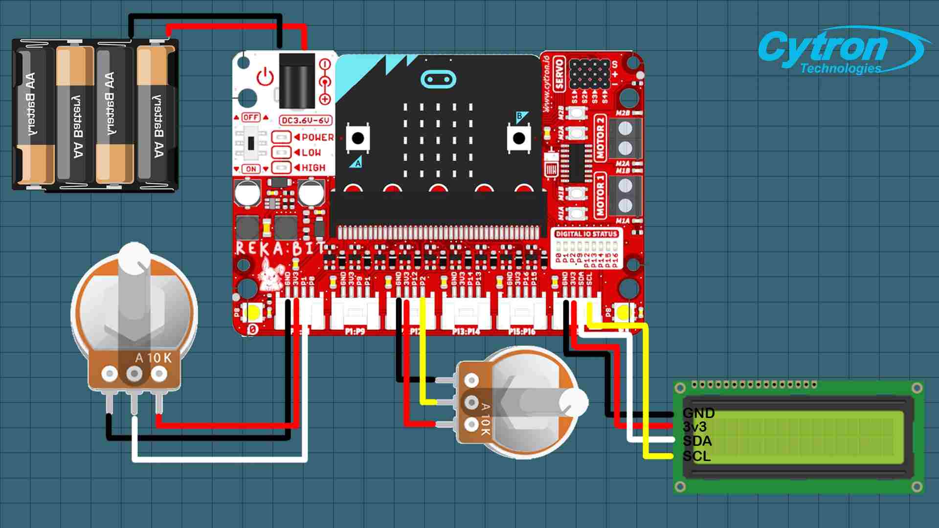
By following the diagram above:
- Connect both of the potentiometers to the 1st and 3rd ports.
- Connect the LCD to the 6th port
Step 5: Code
⚠️ Please check out this tutorial for a clearer understanding of how to use the 3.3V LCD with micro:bit.
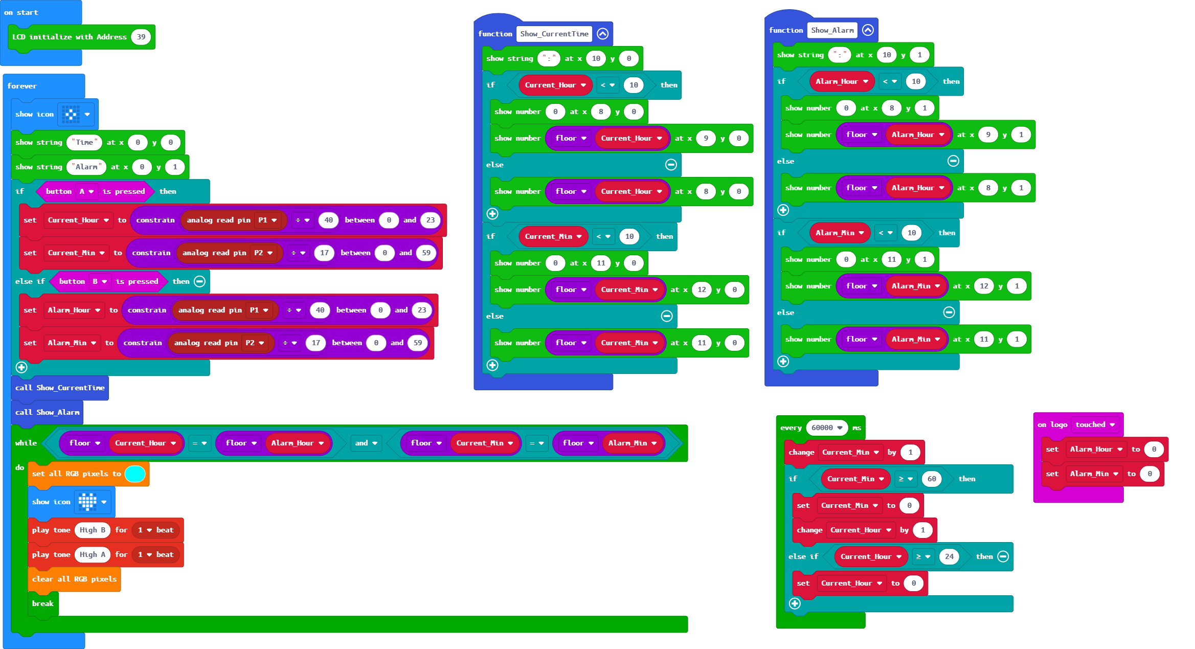
Now, connect your REKA:BIT to your device and open MakeCode editor to start programming.
- Add REKA:BIT extension and follow the code block in the picture above
- After completing the code, download it on microbit
You can also view and edit the code by clicking here!
Project Completed!
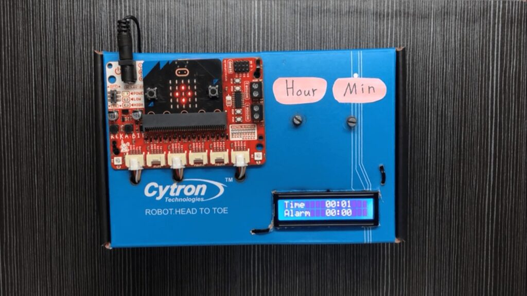
Turn on REKA:BIT and start by adjusting the current time, after that proceed to set the alarm
- Hold A button and rotate the potentiometer to adjust the time
- Hold B button and rotate the potentiometer to set the alarm
Related Products

Potential Meter 10K
S$0.43 S$0.43
x 1 unit(s)

3V3 I2C and SPI 1602 Serial Character LCD
S$6.61 S$6.61
x 1 unit(s)
 - Simplifying Robotics with micro:bit") -10%
-10%REKA:BIT (with micro:bit V2 included) - Simplif...
S$50.71 S$56.07 S$50.71
x 1 unit(s)