 International
 Singapore
 Malaysia
 Thailand
 Vietnam
Your shopping cart is empty!

K-Type Thermocouple With Maker UnoX And Blynk
- Hussien Jawhar Sathik
- 14 Nov 2021
- Tutorial
- 510
Introduction
In this simple video, it is demonstrated how to interface a K-Type thermocouple with Maker UnoX and display the temperature value on the 16x2 LCD and also using Blynk.
What is K-Type Thermocouple?
The thermocouple is a component that is best used for measuring temperatures that go beyond 100 °C. The bare wires bead-probe can measure air or surface temperature. The sensor consists of two dissimilar metal wires joined at one end, and connected to a thermocouple-capable device at one end.
Video
Hardware Preparation
This is the list of items used in the video.
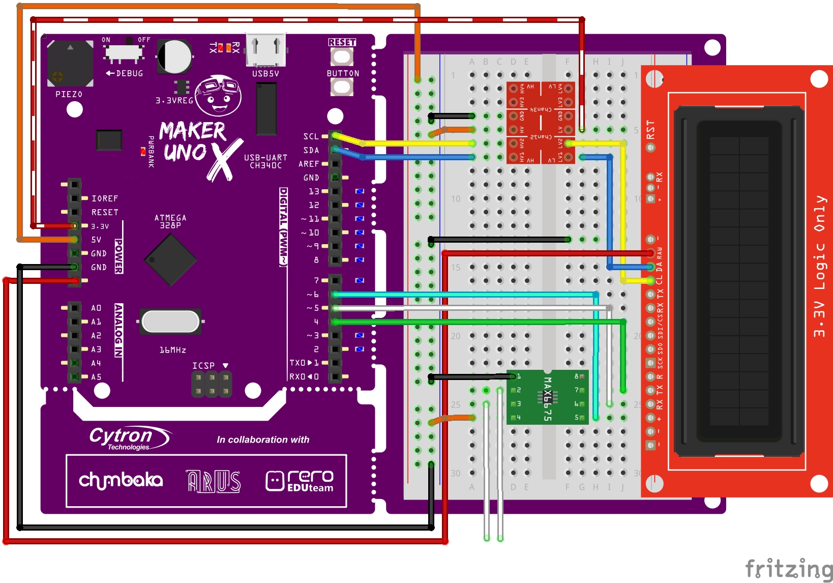
Circuit
The connection between the components is shown in the figure below. The unconnected white colour wire connection is for the thermocouple.
As for the Grove WiFi 8266, the connection is as shown below
| Grove WiFi 8266 | MAKER UNO X |
| GND | GND |
| VCC | 5V |
| RX | 11 |
| TX | 10 |
Code
The code for this tutorial is as shown below
#define BLYNK_PRINT Serial

#include
#include  //Click here to get the library: http://librarymanager/All#SparkFun_SerLCD
#include
#include
#include


//Software Serial on Uno, Nano...
#include
SoftwareSerial EspSerial(10, 11); // RX, TX

//Insert your Blynk project Auth Token
char auth[] = "djigt1lMWzPmqbppsEDxk6uUFNeLzf-C";

// Insert your WiFi credentials.
// Set password to "" for open networks.
char ssid[] = "hotspot";
char pass[] = "hotspot123";


// Your ESP8266 baud rate:
#define ESP8266_BAUD 115200

ESP8266 wifi(&EspSerial);

SerLCD lcd; // Initialize the library with default I2C address 0x72


//#define DISPLAY_ADDRESS1 0x72 //This is the default address of the OpenLCD  that


int thermoDO = 4;
int thermoCS = 5;
int thermoCLK = 6;

MAX6675 thermocouple(thermoCLK, thermoCS, thermoDO);
int vccPin = 7;
int gndPin = 8;

// make a cute degree symbol
uint8_t degree[8]  = {140,146,146,140,128,128,128,128};

void setup() {
  // put your setup code here, to run once:

  pinMode(vccPin, OUTPUT); digitalWrite(vccPin, HIGH);
  pinMode(gndPin, OUTPUT); digitalWrite(gndPin, LOW);

  Wire.begin(); //Join the bus as master


  lcd.begin(Wire); //Set up the LCD for I2C communication
  lcd.createChar(0, degree);

  title();
  delay(1000);

  // Debug console
  Serial.begin(9600);
  delay(10);
  // Open the connection at 115200
  EspSerial.begin(115200);
  EspSerial.println("AT");

  Blynk.begin(auth, wifi, ssid, pass);

}

void loop() {

 Blynk.run();

  // put your main code here, to run repeatedly:
  lcd.setCursor(0,0);

  lcd.clear();
  lcd.print("Temperature: ");
  // go to line #1
  lcd.setCursor(0,1);
  lcd.print(thermocouple.readCelsius());
#if ARDUINO >= 100
  lcd.write((byte)0);
#else
  lcd.print(0, BYTE);
#endif
  lcd.print("C ");


      Blynk.virtualWrite(V1, thermocouple.readCelsius());
  delay(1000);
}


void title()
{
  lcd.clear();
  lcd.setCursor(0,0);
  lcd.print("Thermocouple");
  lcd.setCursor(1,1);
  lcd.print("Temperature");
  delay(2000);
  lcd.clear();
  lcd.setCursor(1,0);
  lcd.print("With Maker Uno");
  lcd.setCursor(3,1);
  lcd.print("And Blynk");
}
Thank You
References:
Thanks for reading this tutorial. If you have any technical inquiries, please post at Cytron Technical Forum.
"Please be reminded, this tutorial is prepared for you to try and learn.
You are encouraged to improve the code for a better application."