 International
 Singapore
 Malaysia
 Thailand
 Vietnam
Your shopping cart is empty!
EdgeBox RPI 200 And CODESYS : Digital Input
- Hussien Jawhar Sathik
- 28 May 2023
- Tutorial
- 854
Introduction
In the previous tutorial we have seen how to get started with EdgeBox RPI 200 and CODESYS. Now we would like to see how to add a digital input to the device and monitor its status through the visualization features in the CODESYS. First let's have a short introduction on the digital input for PLC.
What is "Digital Input"?
Digital inputs are used to monitor the on/off or high/lows state of external devices or sensors, such as pushbuttons, limit switches, proximity sensors, or other similar devices. These inputs are typically wired to the PLC's input modules, which convert the electrical signals from the external device into a digital signal that the PLC can process. The PLC consists of multip,e input channels, each corresponding to an individual input point. Each channel is connected to a specific digital input terminal on the PLC. The module provide isolation and protection for the PLC's internal circuitry.
When the external device associated with a digital input is activated(e.g. a switch is pressed, a sensor destects an object, etc.) the digital input module sends a corresponding signal to the PLC's central processing unit (CPU). The CPU then processes this input information and executes the programmed logic based on the detected states. In PLC programming, digital inputs are typically used as triggers or condition for various control functions and decision making processes. For example, a digital input may be used to start or stop a motor, activate an alarm, control a valve, or initiate a specific sequence of operations.
It is important to note that digital inputs are binary in nature, meaning they can only detect two states: ON (high) or OFF (low). They are not suitable for continous varying analog signals, which require analog input modules for accurate mesurement and processing.
That's a bried introduction on the digital input. Now let's look at the hardware that will needed.
Hardware
For the hardware we will be using the EdgeBox RPI 200. Along with this we would need the following item,
- 24VDC power supply
- push button
- and wire
The wiring connection are done as shown in the figure below
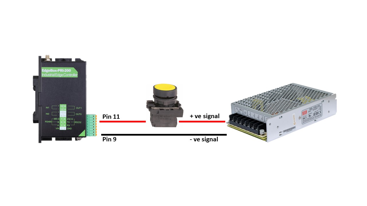
The other connection such as the power and ethernet connection remains the same.
Software
For the software part the steps are as follows.
1. Start the CODESYS and connect it to the EdgeBox. Please refer to the getting started tutorial here. Once it is connected move to the next step.
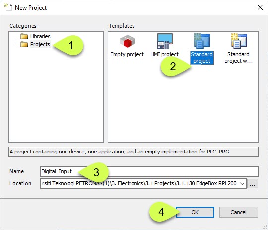
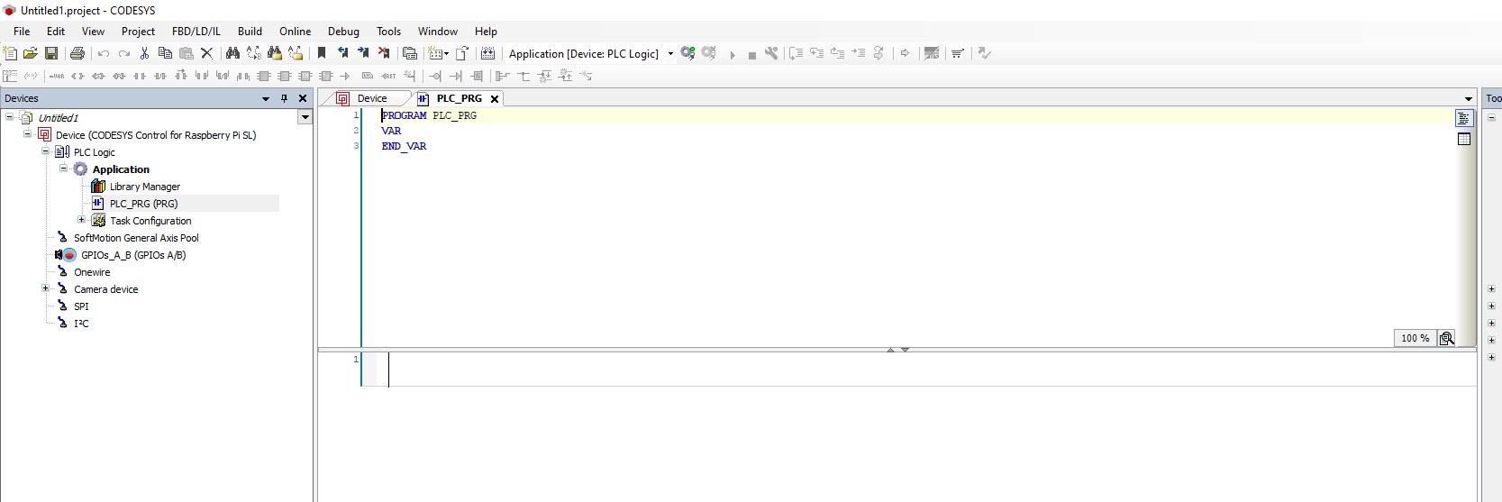
2. In the standard project, choose the Device, PLC_PRG in as shown in the figure below

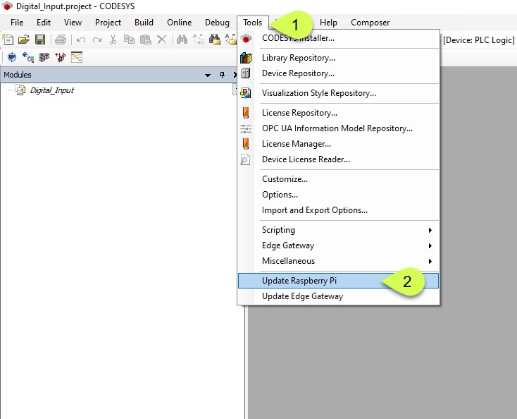
3. Next go to Tools --> Update Raspberry Pi
4. Key in the credentials as follow:
- passsword : raspberry
- IP address : 192.168.68.110
And click the start button
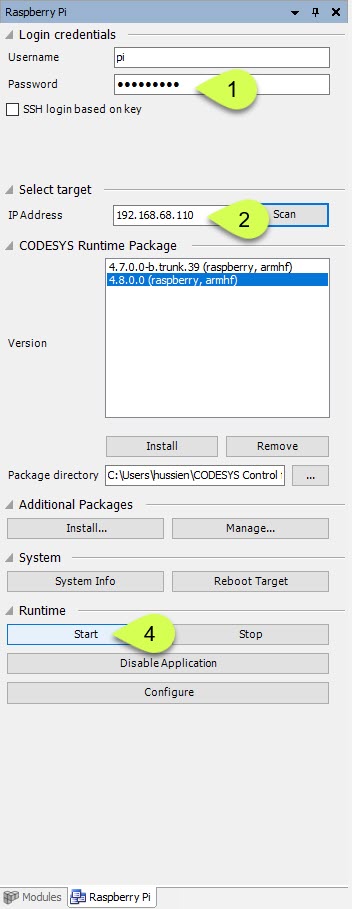
5. If everything goes well, can see the message "codesyscontrol started"

6. Double click the PLC_PRG(PRG)

7. This open the window for ladder diagram programming
8. Click the one shown in the figure below
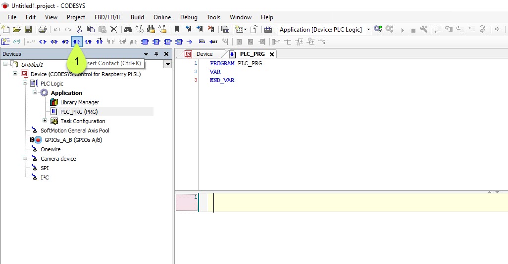
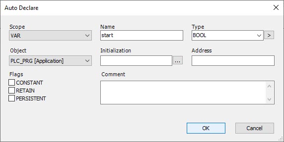
8. And rename it to "start" and press enter

9. When this window pop up, click OK
10. Click the square button as shown in the figure below and press the insert coil symbol.

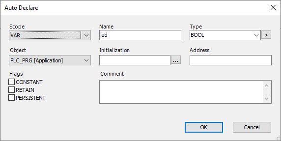
11. Rename the coil contact to "led" and press enter
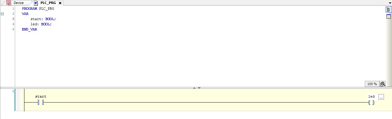
12. Press OK
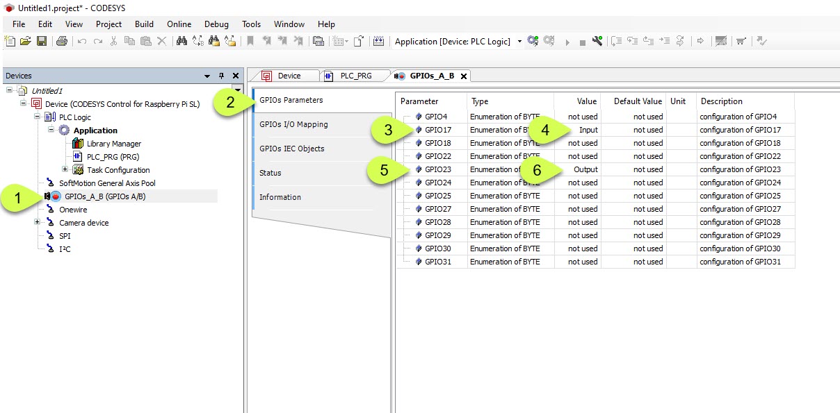
13. Next go to GPIOs_A_B --> GPIOs Parameters and change the value for GPIO 17 and GPIO 23 accordingly(refer to figure below).
Note: the reason to choose the GPIO as input or output is referred to datasheet.
14. Next is to update the GPIOs I/O Mapping. Go to GPIOs_A_B --> GPIOs I/O Mapping and choose Bit 17. Make the changes as shown in figure below.

15. Next is to update the GPIOs I/O Mapping. Go to GPIOs_A_B --> GPIOs I/O Mapping and choose Bit 23. Make the changes as shown in figure below.

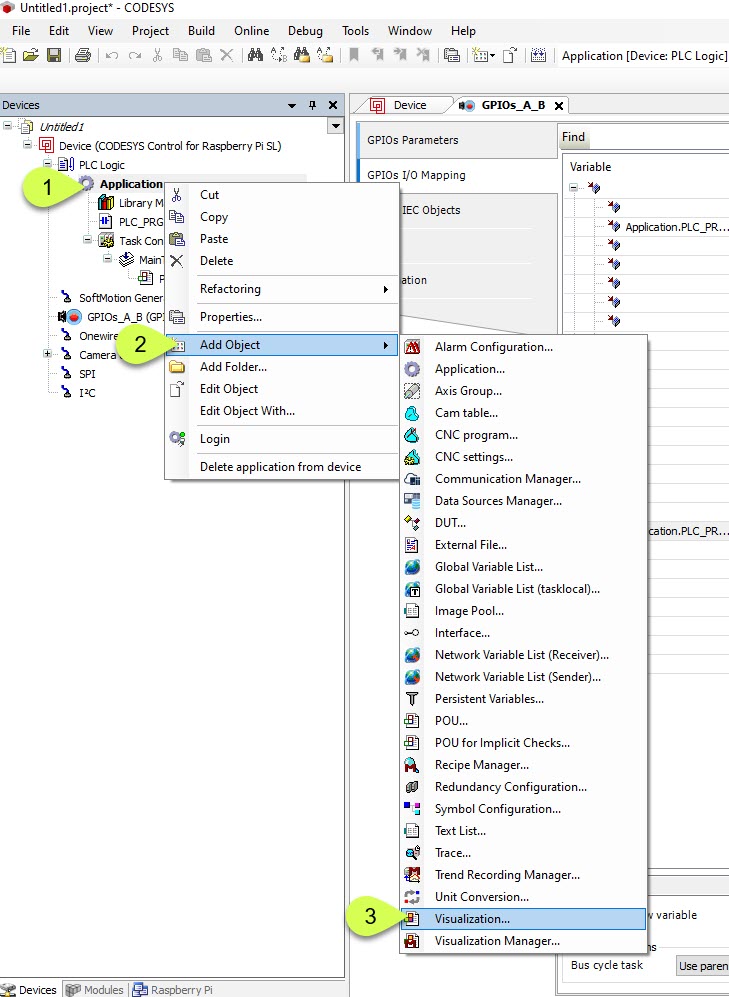
16. Once we are done with configuring the GPIO, we can now setup the visualization. Right click on the "Application" --> Add Object and choose Visualization
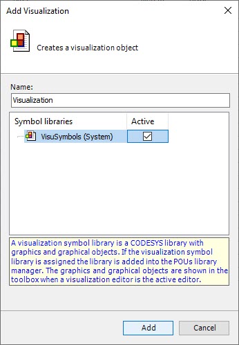
17. When a window pop-up, tick the active and click Add.
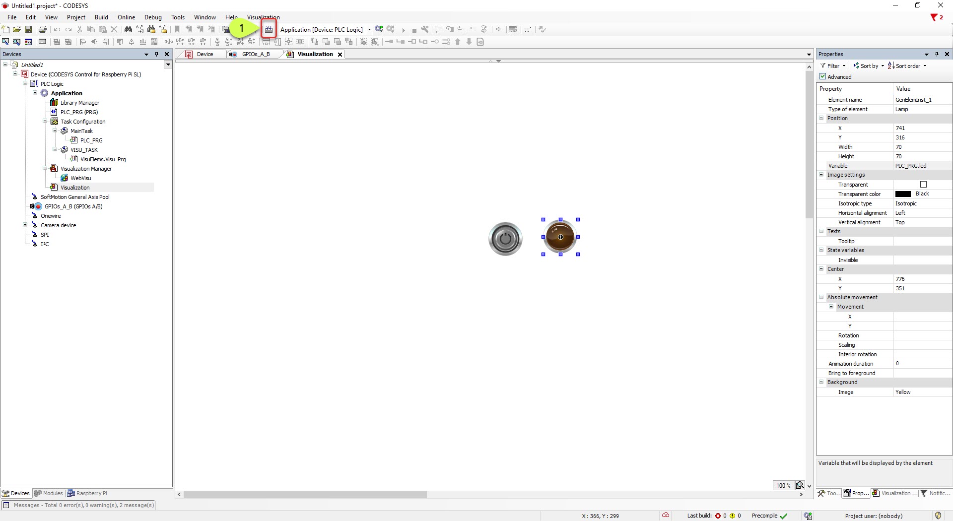
18. A visualization window will appear. Choose Lamps/Switches/Bitmaps and choose the item as shown in the figure below.

19. Now we want to configure the lamp. Follow the steps shown in the figure below. Once done click OK
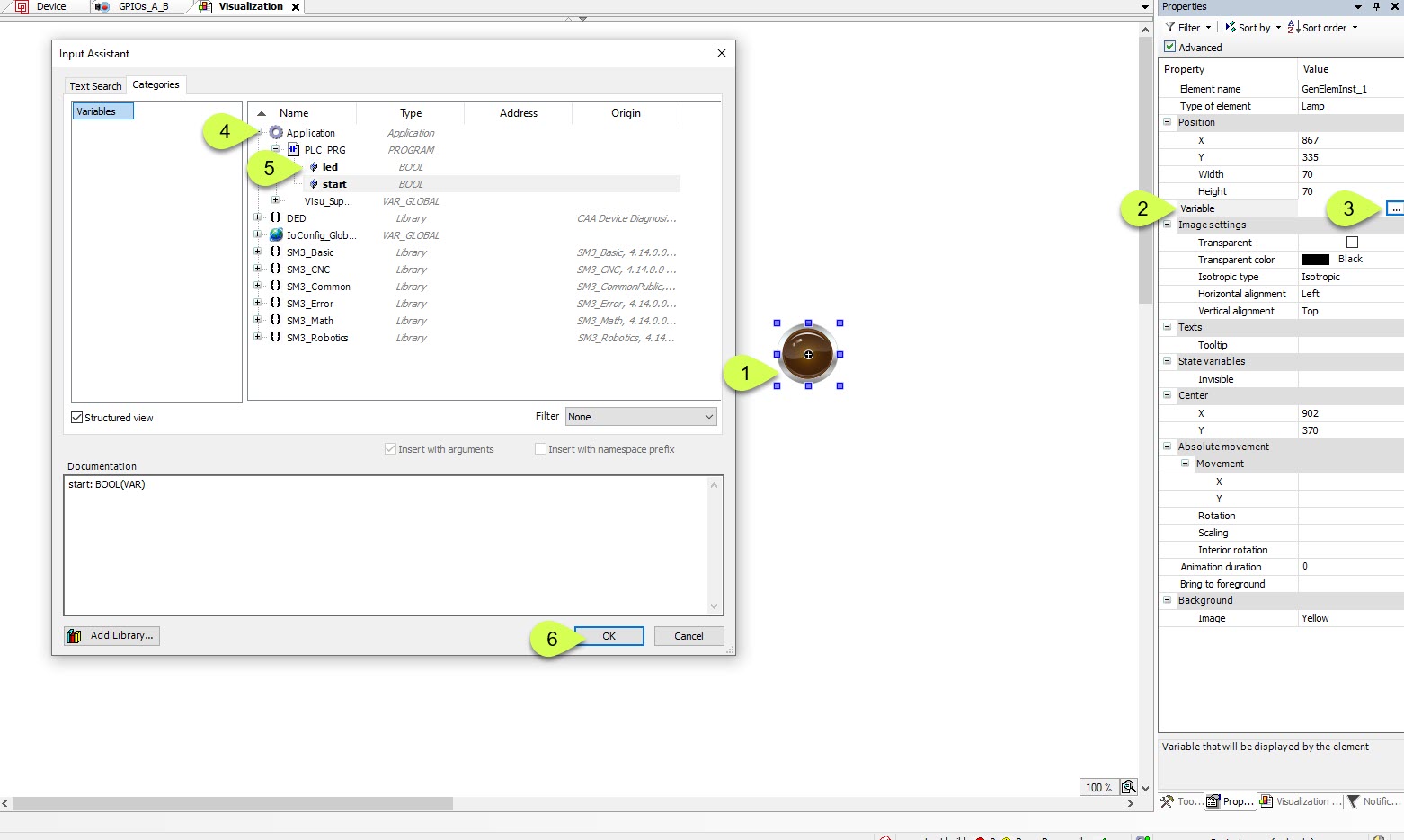
19. Now we want to configure the switch. Follow the steps shown in the figure below. Once done click OK

20. Click the generate code button
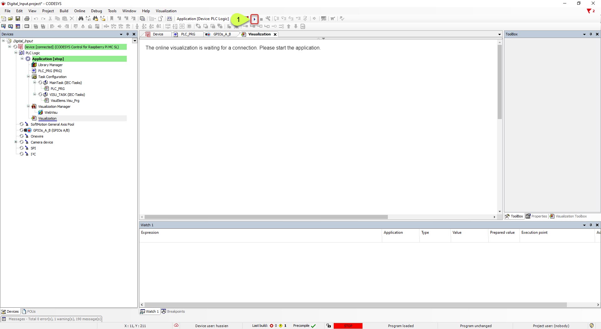
21. Next click the login button

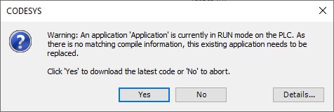
22. When this window pops-up. Click YES
23. Clcik the Play button.
24. Now its ready. When the push button is not pressed the LED remain off.
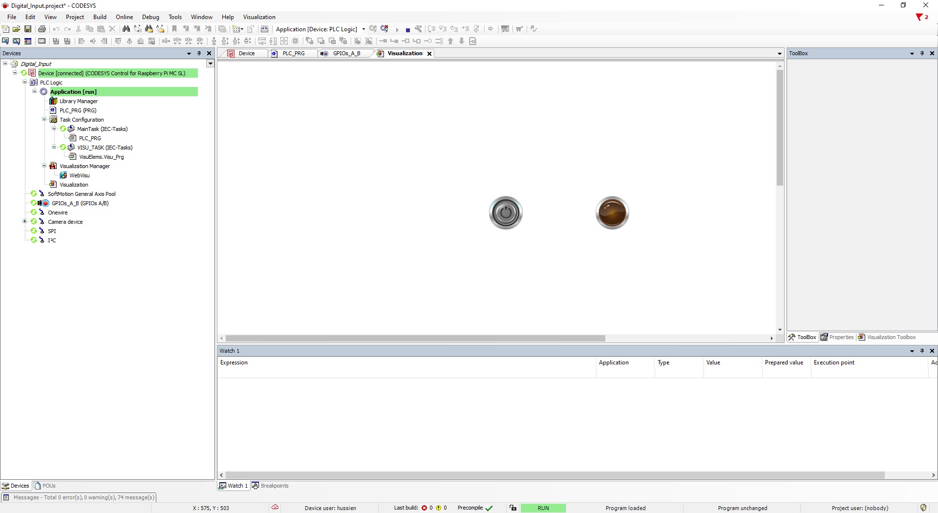
25. When the button is pressed, the LED lights up

Demo
This is the demo of the tutorial