 International
 Singapore
 Malaysia
 Thailand
 Vietnam
Your shopping cart is empty!

Part 3: Digital Output with Cytron IRIV PiControl and CODESYS
- Huck Phin Ch’ng
- 29 Jul 2024
- Tutorial
- 229
This is a sample output of what we will achieve at the end of this section - the ability to toggle the LED built into the momentary push button on and off from a button press, programmed with CODESYS
Introduction
In the previous part, we explored using the digital input port with Cytron IRIV PiControl and CODESYS. In this part, we will build upon that and explore the digital output port with Cytron IRIV PiControl and CODESYS.
What is "Digital Output"?
Digital PLC outputs are circuits that utilise binary data (1 and 0) to enable the PLC CPU to control external output devices. Essentially, a digital PLC output refers to the processed binary control signal sent from the PLC to the field devices. These outputs are commonly employed to establish an ON or OFF (OPEN or CLOSED) control mechanism for the connected PLC's managed devices or systems.
Types of Digital PLC Outputs
There are three main types of digital PLC outputs available:
Relay PLC Outputs: These outputs are capable of controlling both DC (Direct Current) and AC (Alternating Current) field devices. Relay outputs offer low resistance control with a current capacity of up to 2A (Amperes). They are commonly used in various industrial applications.
Transistor PLC Outputs: Transistor outputs are voltage-dependent and suitable for operating DC loads. These outputs are commonly utilised in low-power DC circuitry, including microprocessors. They are especially useful in applications that require fast switching operations, such as controlling lights.
TRIAC PLC Outputs: TRIAC stands for Triode for Alternating Current. TRIACs are solid-state electronic switches made of silicon, which can be activated by a small control voltage from a PLC. Similar to MOSFET transistors, TRIACs are commonly used for controlling low-power AC loads, including motor starters, lighting systems, and contactors.
By understanding the differences and characteristics of these digital PLC output types, you can select the most appropriate one for your specific application requirements.
Examples of Digital Field Output Devices in PLCs
Digital PLC outputs can control various field output devices in industrial applications. Here are some examples:
A) Indicator Lights
The simplest example is a light bulb or indicator light. A digital output from the PLC can turn the light bulb ON or OFF. Green/Red pilot lights are also controlled similarly, indicating the status of a machine or system. For instance, a digital PLC output can turn ON the Red pilot light to indicate a malfunction.
B) Alarms
PLC-controlled systems often include alarms to notify of critical conditions. This can be achieved using a horn, blinking red light, or buzzer. Buzzer alarms can be programmed to vary ON duration or ON/OFF intervals to convey different urgency levels.
C) Actuators
Actuators convert electrical or control signals into mechanical motion. They enable the PLC's digital output to drive practical movements. Actuators are commonly used with high-power AC or DC voltage sources and have coils that allow small DC voltage to control their switching.
D) Solenoid Valves
Solenoid valves are electromechanical valves controlled by an electrical signal. There are two common types: Direct Acting and Pilot Operated. Solenoid valves control the flow direction of fluids in hydraulic and pneumatic systems. When a DC control voltage is applied to the solenoid from the PLC, it creates a magnetic field that opens the valve by moving the ferromagnetic plunger. Removing the control voltage allows the spring to close the valve.
These examples demonstrate how digital PLC outputs can effectively control a range of field output devices in industrial automation systems.
In this tutorial, we shall see how to control a simple LED. Let's see the hardware used in this tutorial.
Hardware
To complete this part of the tutorial, we will need the following hardware:
Cytron IRIV PiControl
24V DC power supply
Momentary push button
22AWG Hook Up Wire
The wiring connection between the hardware pieces is shown in the figure below

Software
Open CODESYS and open the IRIV Codesys Tutorial project we last worked on during the Digital Input with Cytron IRIV PiControl and CODESYS part.
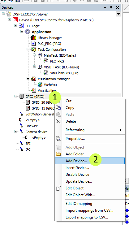
Right-click on the GPIO and choose Add Device.
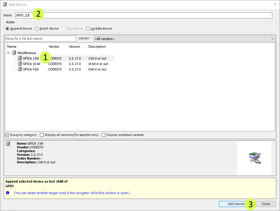
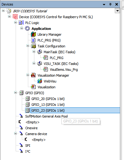
Choose GPIOs 1 Bit, enter GPIO_23 for the Name, and click Add Device.
Referring to the IRIV PiControl Datasheet, the Digital Output 0 port is mapped to GPIO 23.
Double-click on the GPIO_23 to bring it’s the configuration window
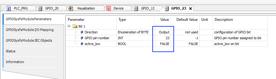
In the GPIO_23 configuration window, select the first tab "GPIOSysfsModuleParameters" to configure and assign the GPIO Direction, GPIO Pin Number, and current PIN state accordingly (refer to the figure below)

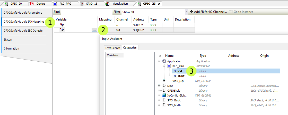
Next, go to the GPIOSysfsModule I/O Mapping and assign the led variable accordingly (refer to figure below)
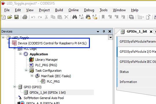
Next, we want to login into the IRIV PiControl to online mode. First, we need to double-click the "Device (CODESYS Control for Raspberry Pi…)".
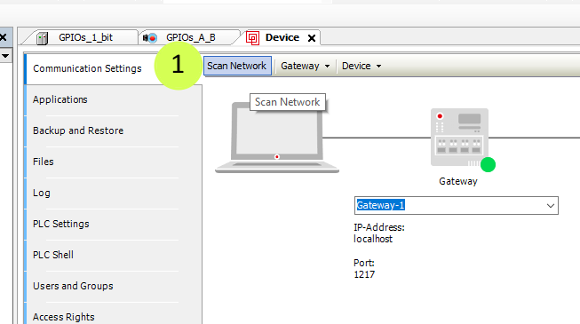
The device configuration window will open.
In the communication settings window, click on Scan Network
Next, select Cytron IRIV PiControl under “Gateway” and then click Ok

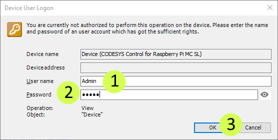
Type in "Admin" for the Name and "admin" for the Password. Then click OK.
NOTE: If you used custom particulars for the name, password and confirm password earlier, use your custom particular instead.
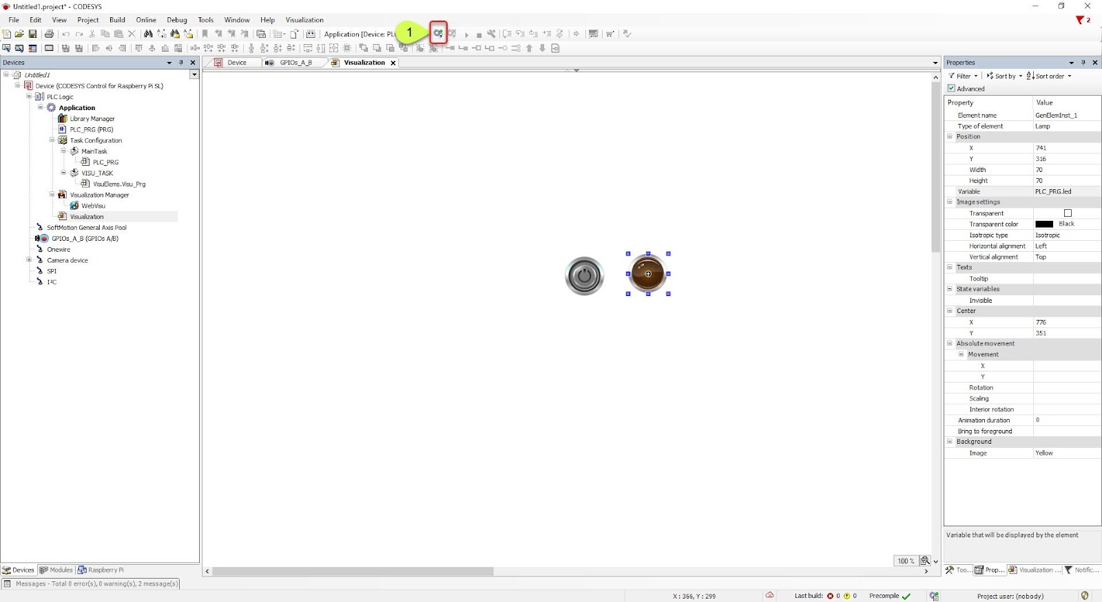
Next, click the login button
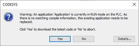
When this window pops up. Click Yes
Click the Play button.
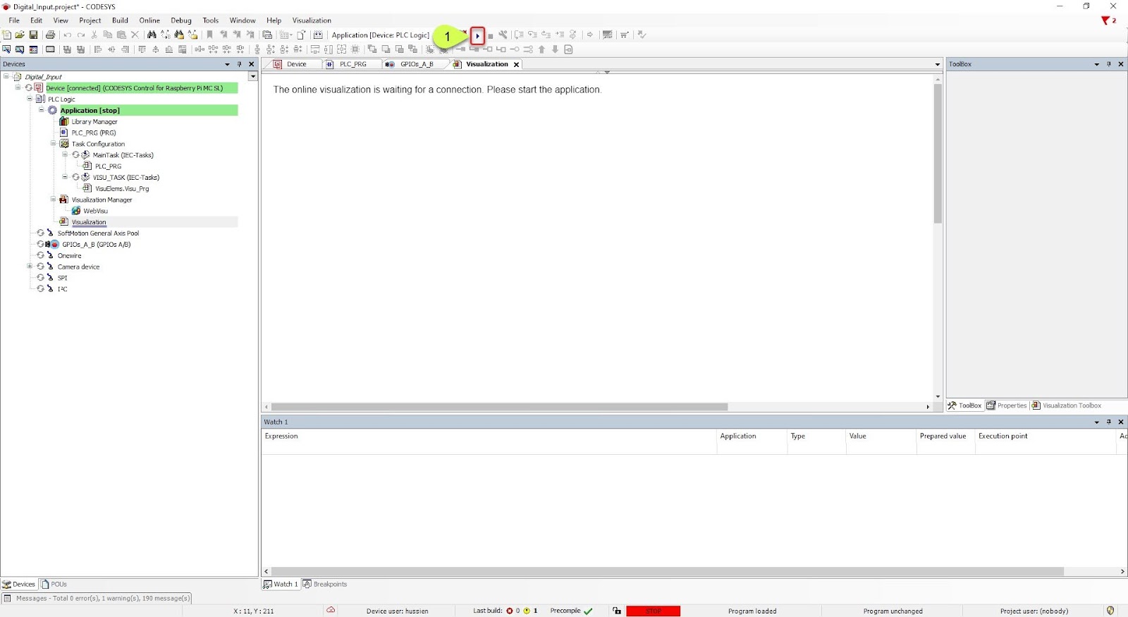
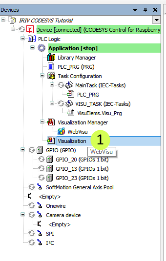
Double click on Visualization from the leftmost pane to return to the visualisation
Now it's ready. Now it's ready. When the momentary push button is pressed, the LED built into the momentary push button will turn on.

When the momentary push button is not pressed, the LED built into the momentary push button will not turn on.

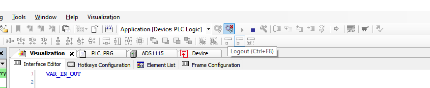
Before ending, click the tool button highlighted in the figure below (Logout) to safely logout.
Hardware Components

IRIV PiControl - IR4.0 CM4 Industrial Controller
S$420.00++ S$420.00
x 1 unit(s)