 International
 Singapore
 Malaysia
 Thailand
 Vietnam
Your shopping cart is empty!

Part 4: Analog Input with Cytron IRIV PiControl and CODESYS
- Huck Phin Ch’ng
- 29 Jul 2024
- Tutorial
- 215
This is a sample output of what we will achieve at the end of this section - the ability to read an analog input connected to Cytron's IRIV PiControl in CODESYS

Introduction
In the previous part, we explored using the digital output port with Cytron IRIV PiControl and CODESYS. In this part, we will build upon that and explore the analog input port with Cytron IRIV PiControl and CODESYS.
What is "Analog Input"?
Analog inputs in a PLC (Programmable Logic Controller) are used to measure continuous signals from external devices or sensors. Unlike digital inputs that detect binary states (ON/OFF), analog inputs can detect a range of values and provide a more detailed representation of the physical conditions being monitored. Examples of analog signals include temperature, pressure, humidity, voltage, and current.
These inputs are connected to the PLC's analog input modules, which convert the continuous signals into a digital format that the PLC can process. The conversion process involves Analog-to-Digital Converters (ADCs) that sample the incoming analog signal and convert it into a corresponding digital value. The resolution of the ADC determines the accuracy and granularity of the measurement.
Analog inputs are crucial for applications that require precise monitoring and control. For instance, in a temperature control system, an analog input can provide the exact temperature reading to the PLC, which then adjusts the heating or cooling system accordingly. Similarly, in a pressure monitoring system, the analog input can continuously provide pressure readings, allowing the PLC to maintain the desired pressure levels.
Hardware
To complete this part of the tutorial, we will need the following hardware:
Cytron IRIV PiControl
24V DC power supply
Momentary push button
22AWG Hook Up Wire
3.3V and 5V DC source
NOTE: For demonstration in this tutorial, we will use an Arduino board for our 3.3v and 5v DC source.
The wiring connection between the hardware pieces is shown in the figure below

Software
First download 2 files here and here. These 2 files are the device description and device library files required by CODESYS to communicate with the ADS1115 analog-to-digital converter (ADC) on the IRIV PiControl.
Then open CODESYS and open the IRIV Codesys Tutorial project we last worked on during the Digital Output with IRIV PiControl and CODESYS part.
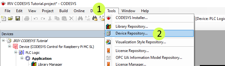
Go to the Tools menu from the top toolbar and then click Device Repository….
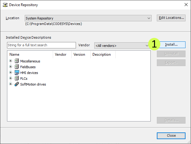
Click on Install…
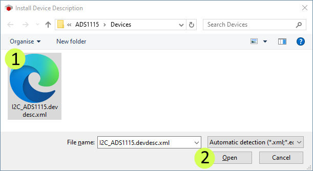
Select the I2C_ADS1115.devdesc.xml file downloaded earlier and click Open
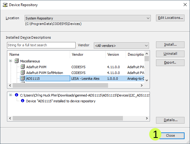
Click Close
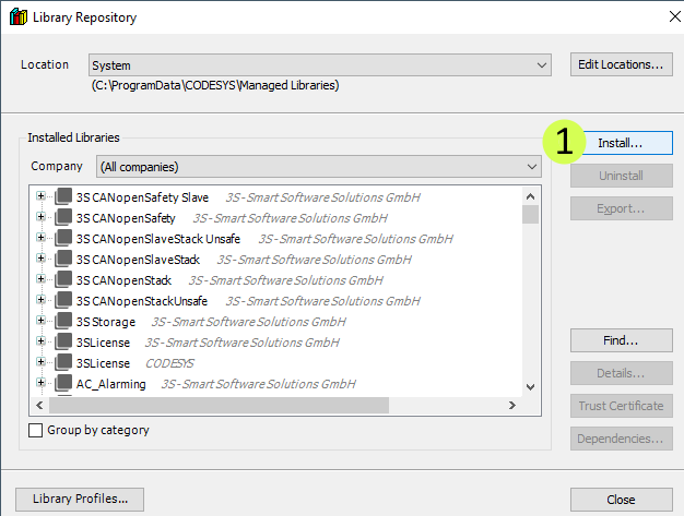
Go to the Tools menu from the top toolbar and then click Library Repository…

Click on Install…
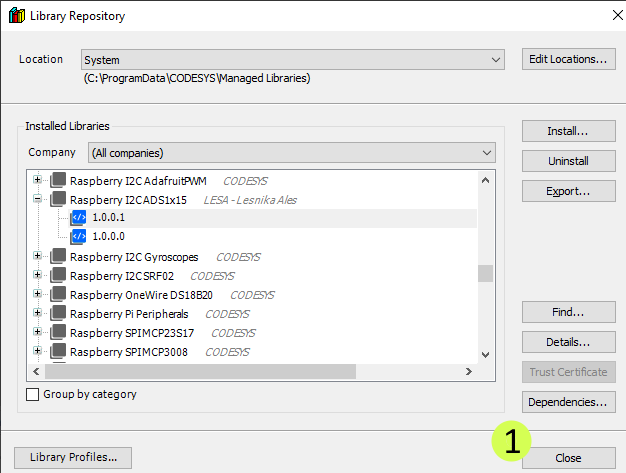
Select the I2C_ADS1x15.library file downloaded earlier and click Open

Click Close
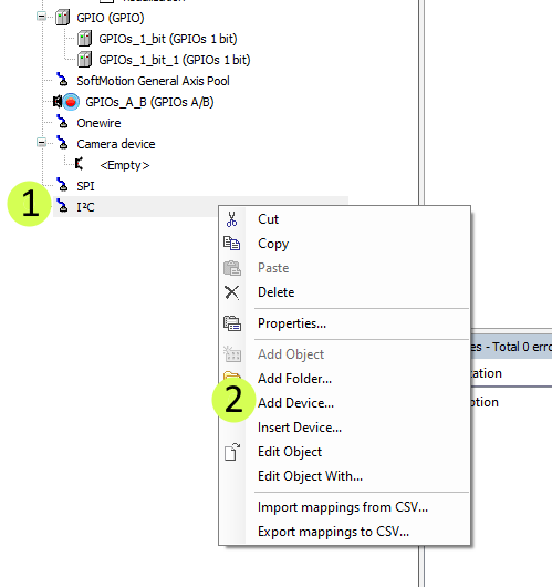
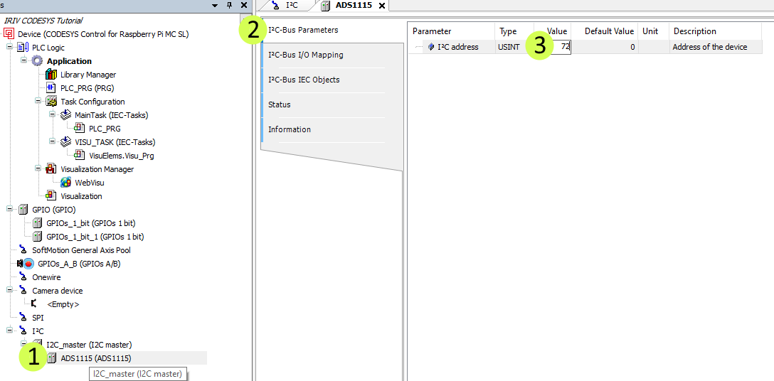
Right-click on I2C and click Add Device…
Select I2C master and click Add Device

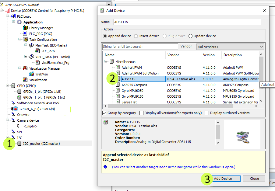
Click I2C_Master (I2C master) from the left pane. Then in the Add Device window, select ADS1115 and click Add Device
Double-click on ADS1115 (ADS1115) from the left pane. Then click on I2C Bus Parameters. Enter 72 under the Value column.
Double click the PLC_PRG(PRG)
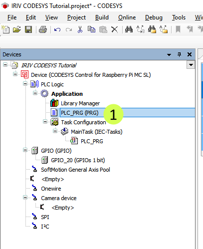
This opens the window for structured text programming
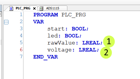
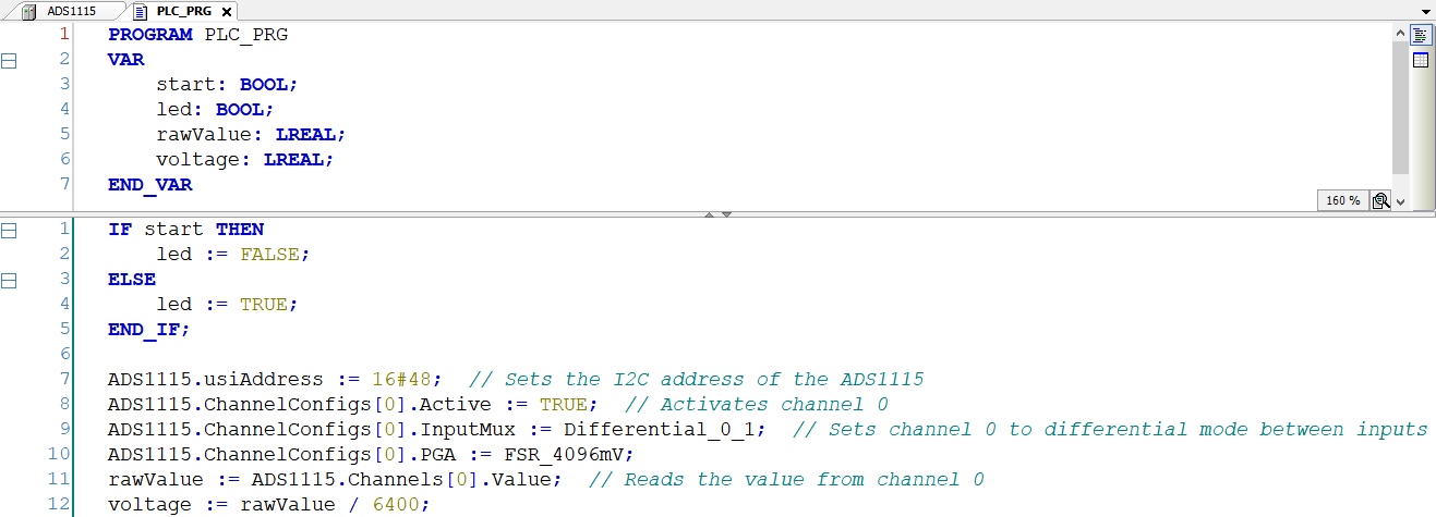
Type in 2 lines of variable declaration in line 5 and line 6
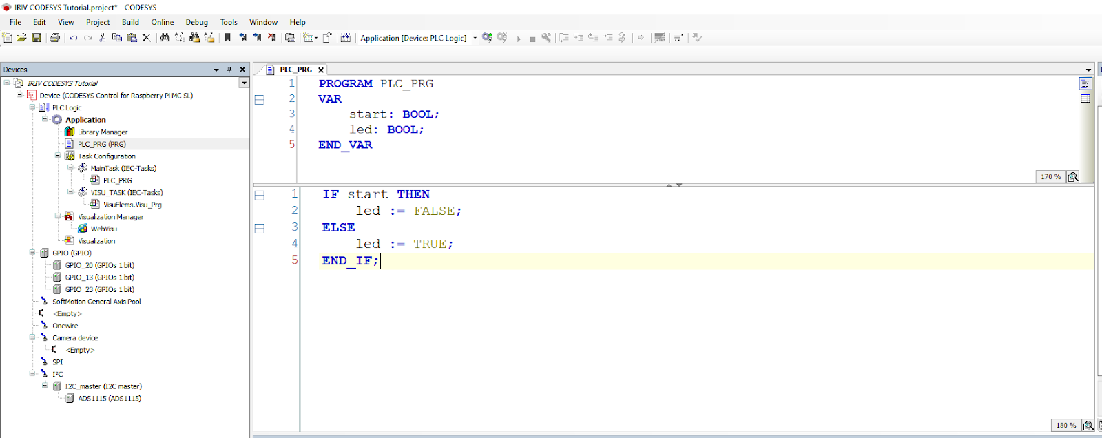
In the separate logic implementation section, type in the following 6 lines of code as per in the figure below
ADS1115.usiAddress := 16#48; // Sets the I2C address of the ADS1115
ADS1115.ChannelConfigs[0].Active := TRUE; // Activates channel 0
ADS1115.ChannelConfigs[0].InputMux := Differential_0_1; // Sets channel 0 to differential mode between inputs 0 and 1
ADS1115.ChannelConfigs[0].PGA := FSR_4096mV;
rawValue := ADS1115.Channels[0].Value; // Reads the value from channel 0
voltage := rawValue / 6400;
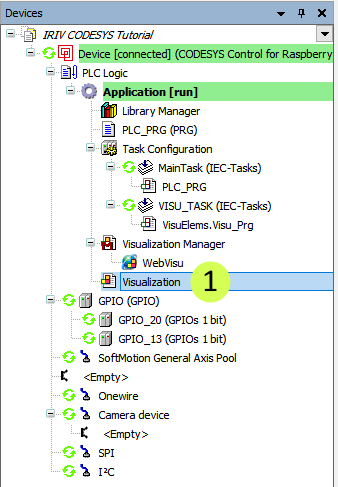
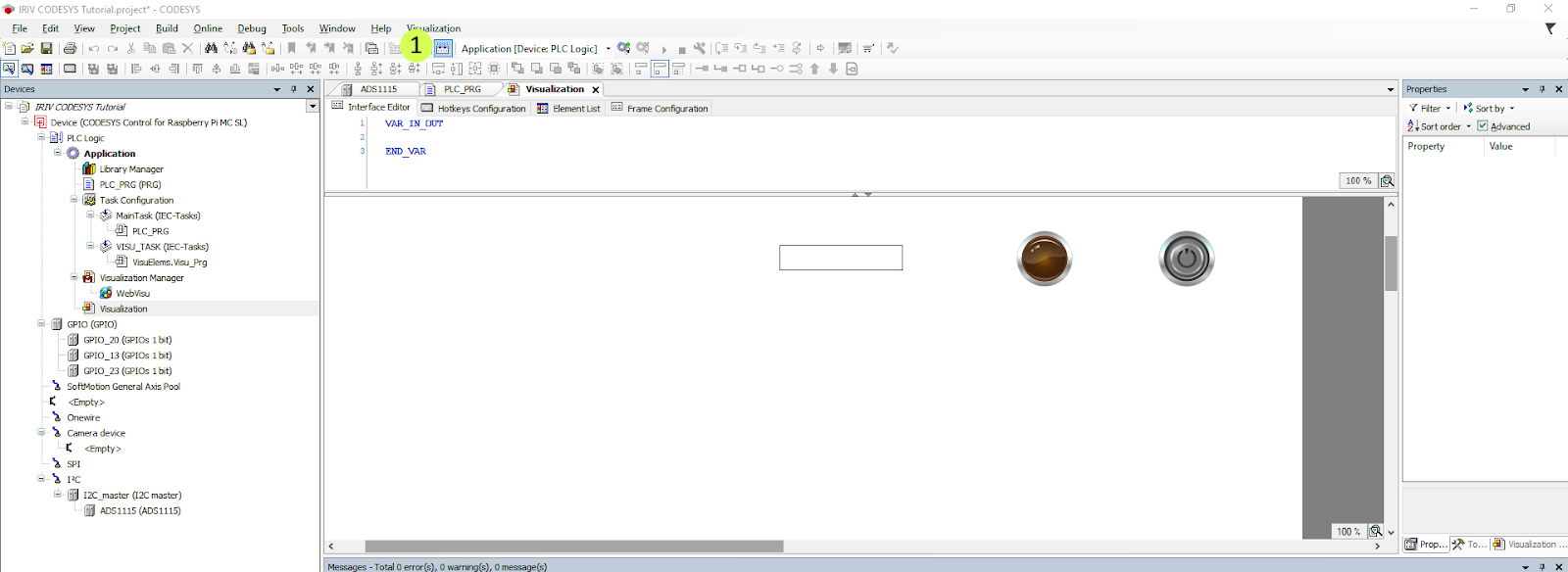
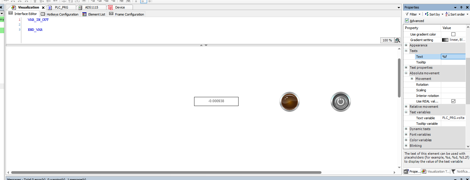
Double click on Visualization from the leftmost pane to return to the visualisation
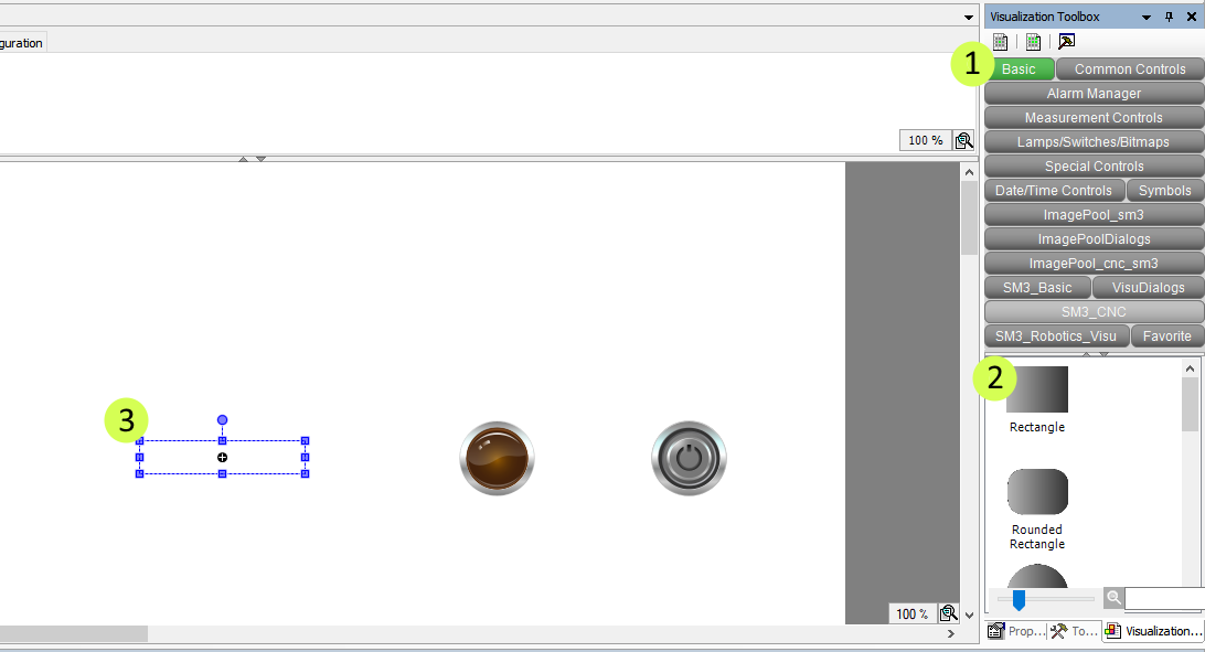
A visualisation window will appear. Choose Basic and drag a rectangle to the visualisation canvas.
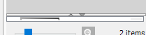
NOTE: If you don’t see the items below the categories, click on the small up arrow below the categories.
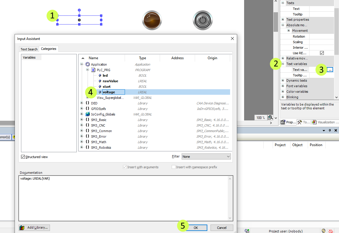
Now we want to configure the rectangle to display the value from the analog input. Click on the rectangle, then select the three dots next to Text variable in the properties pane. Expand the application, expand PLC_PRG, and select voltage. Click OK.
Then enter %f as placeholder text as shown in the figure below

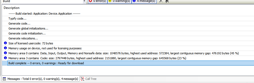
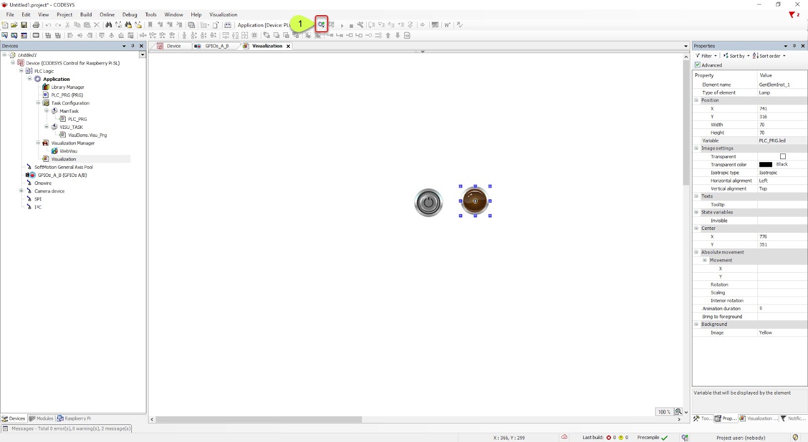
Click the Generate Code button
When you see the message Build complete - 0 errors, 0warnings: Ready for download, the Generate Code step was successful
NOTE: If you encounter compilation errors like Cannot Convert Type, you can first try to go to the Build menu from the top toolbar and then click Clean all. Then acknowledge the pop-up window by clicking Yes.

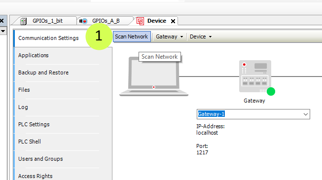
Next, we want to login into the IRIV PiControl to online mode. We must double-click the "Device (CODESYS Control for Raspberry Pi…)".
The device configuration window will open.

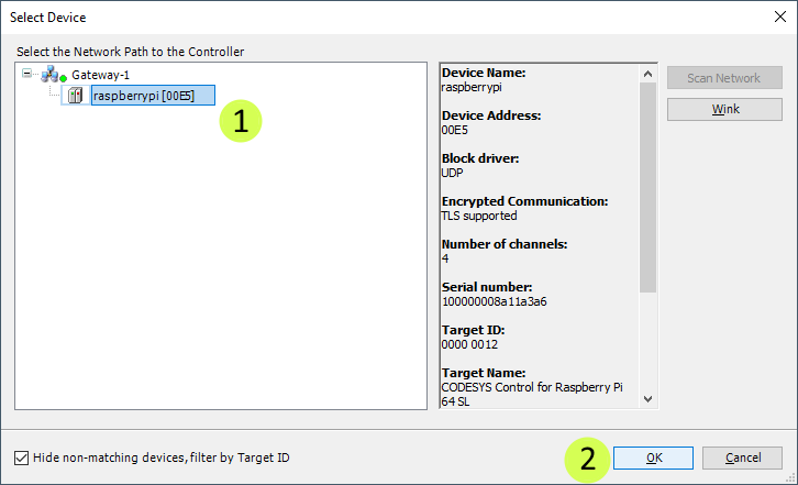
In the communication settings window, click on Scan Network
Next, select IRIV PiControl under “Gateway” and then click Ok
Type in "Admin" for the Name and "admin" for the Password. Then click OK.
NOTE: If you used custom particulars for the name, password, and confirm password earlier, use your custom particular instead.

Next, click the login button
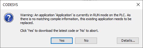
When this window pops up. Click Yes
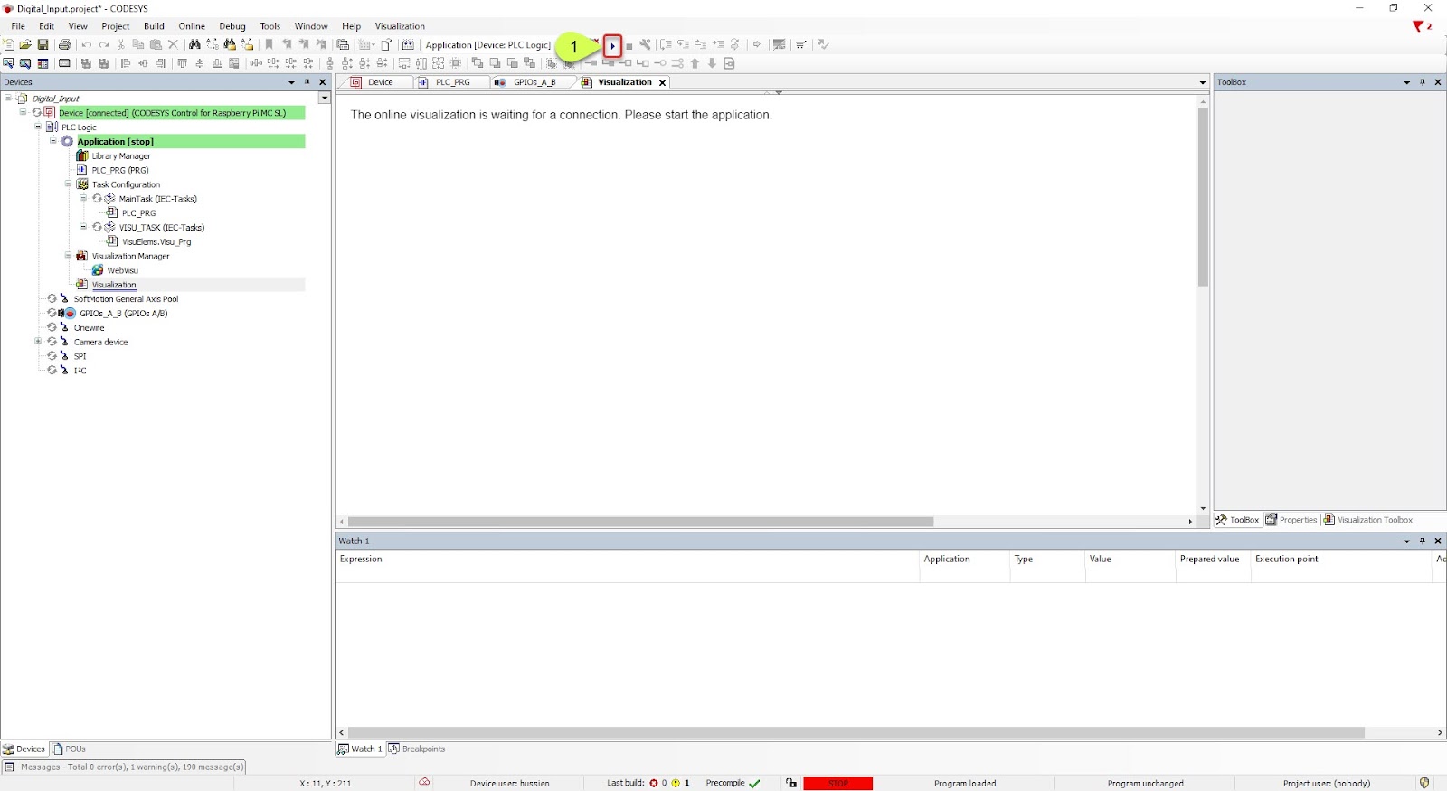
Click the Play button.
Double click on Visualization from the leftmost pane to return to the visualisation
Now it's ready. The analog input reading will be displayed in the rectangle.
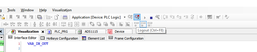
Before ending, click the tool button highlighted in the figure below (Logout) to safely logout.
Hardware Components

IRIV PiControl - IR4.0 CM4 Industrial Controller
S$420.00++ S$420.00
x 1 unit(s)