 International
 Singapore
 Malaysia
 Thailand
 Vietnam
Your shopping cart is empty!

Sensing: Vibration and Tilt
- geneccyann
- 04 Apr 2015
- 1595
Hello everyone! Today I am going to discuss 2 types of useful sensors: Vibration Sensor and Tilt Sensor. Both these products are available on Cytron's website. This tutorial will be separated into 2 parts.
Part 1: Tilt Sensor: Saving Students' Lives
About Tilt Sensor Module SN-TILT-MOD
The tilt sensor module is equipped with a tilt sensor and a potentiometer. You may attach it to any object and it will determine whether the object is tilted or not. It is simple as it returns a digital output. It uses SW-460D or SW-520D tilt sensor. This tilt sensor is a ball-rolling type, NOT the Mercury type.
It comes with a M3 mounting hole for ease of attaching it to any object. A power LED and a status LED are attached to the module for the visual indicators.
This module will output logic LOW when the sensor is tilted below the threshold angle; logic HIGH when it is tilted above the threshold angle. The threshold angle ranges from 45 degrees to 130 degrees. Aside from the threshold angle, angular velocity also affect the tilt module. It can also be used as a vibration sensor, too!
This module can be interfaced with any microcontroller with digital input such as PIC, SK40C, and Arduino series for tilt detection capability. Also, not to forget, interfacing the module with a Relay module forms a tilt switch :)
Features:
- Operating voltage: 3.3 to 5VDC
- Ball Rolling type of tilt sensor.
- PIN: VCC = 5V, GND = 0V, DO = digital output from module
- AO is not used in this module.
* If the DO is not working, you might need to turn the onboard potentiometer to the center.
Application
Introduction
As a student myself, I do not find lecture sessions to be the most entertaining thing to attend. In fact, there are only 2 cases when lectures can be interesting: either the lecturer is super cute and handsome ;) or you have a deep interest in that subject. Sadly, most university students suffer from sleep deprivation because they tend to stay up late the night before either to finish up assignments and projects, play games, or hang out. The worse thing is if they have an 8:00 AM lecture the next day.
and slowly..... he or she becomes a sleeping beauty. It's all cozy and nice until your lecturer bust you out. That would be embarrassing, eh?
Introducing the Lecture Alarm! An alarm that will automatically turn on whenever your head feels heavy and starts tilting.
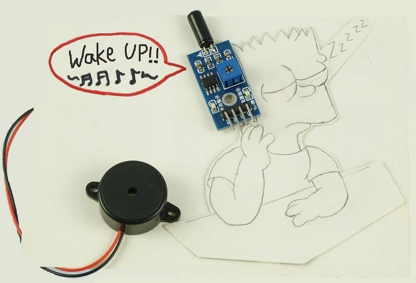
Components:
- 1X CT-UNO
- 1X Buzzer
- 1X 2k2 ohm resistor
- 1X Tilt sensor module
- 1X NPN2222 transistor
- Male-to-male jumper wires
- Male-to-female jumper wires
- 1X USB Cable
- 1X 12V DC power adapter
- 1X half breadboard
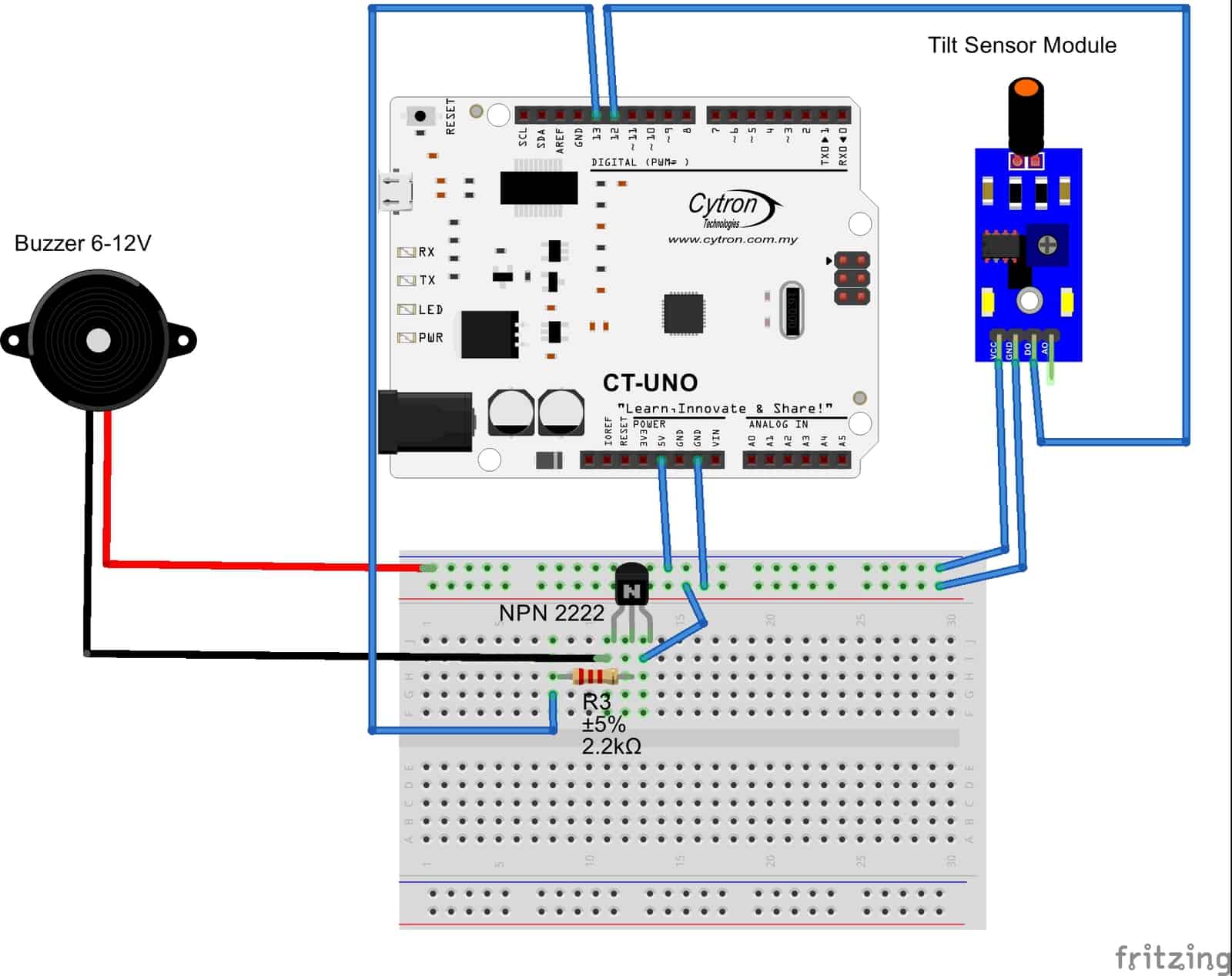
Set up diagram
The diagram above shows the connection of the CT-UNO, Tilt sensor module, and buzzer.
Pin connection of Tilt Sensor Module
- The Vcc pin on the tilt sensor module is connected to the Vcc on the breadboard.
- The GND pin on the tilt sensor module is connected to the GND on the breadboard
- Do pin gives out a digital signal and is connected to pin 3.
- Ao is not connected.
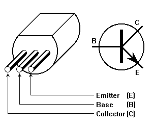
Pin connection of NPN transistor N2222
The diagram above shows the pins of the NPN transistor. Why do I use a transistor? To prevent high current sinking to occur. When dealing with a buzzer, it is advisable not to connect it directly to your UNO or any microcontroller.
CT-UNO uses ATmega328p. Its maximum current per I/O pin is 40mA (Please note also: the maximum total supply is 200mA). If you don't know the specifications of the buzzer, you can manually measure it.
Step 1: Your buzzer should have '+' terminal and '-' terminal marked. Connect the '+' of the buzzer to the positive terminal of a 5V power supply
Step 2: Use a digital multimeter (DMM) to connect the '-' of the buzzer.
Step 3: The negative terminal of the DMM is connected to the negative terminal of the 5V power supply.
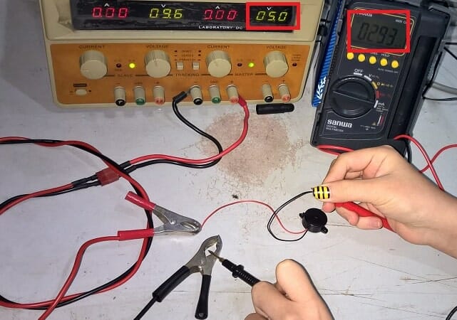
Measuring the current flowing through buzzer in 5V power supply (I = 2.93mA)
We can see that the current drawn by the buzzer is 2.93mA. Although it does not exceed the current limit of one Arduino I/O pin can supply, it is still safer to put a transistor.
If the buzzer draws more current than the uC I/O can supply, you can try adding a resistor according to the current, but it probably won't work or work out of the specifications. A NPN transistor will help you.
Program
[code lang="c" highlight=""]
#define Tilt 2 //Digital output from tilt sensor module is connected to D2
#define BUZZER 3 //LED at D3 pin
void setup() {
//setup the input or output pin
pinMode(BUZZER, OUTPUT);
pinMode(Tilt, INPUT);
digitalWrite(BUZZER, LOW); //off LED
}
void loop() {
if(digitalRead(Tilt)) //if the DO from Tilt sensor is low, no tilt detected.
//You might need to adjust the potentiometer to get reading
digitalWrite(BUZZER,HIGH);
else
digitalWrite(BUZZER,LOW);
}[/code]
LCD Keypad Shield
You can also use an LCD to display some messages. I am using a LCD Keypad Shield.
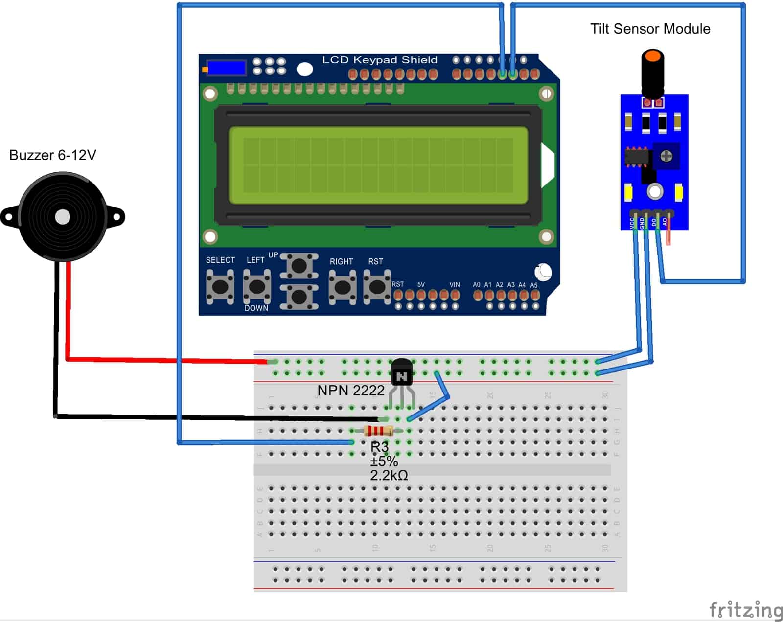
Set up diagram with LCD Keypad Shield
NOTE: LCD Keypad Shield is using pin 4 to pin 9. Do not use these pins for other purposes.
Program
[code lang="c" highlight=""] /* The circuit: * 16x2 character LCD to ARDUINO UNO * LCD RS pin to digital pin 8 * LCD Enable pin to digital pin 9 * LCD D4 pin to digital pin 4 * LCD D5 pin to digital pin 5 * LCD D6 pin to digital pin 6 * LCD D7 pin to digital pin 7 * LCD R/W pin to ground Tilt Sensor module to Arduino UNO *VCC to 5V *GND to GND *Do to D2 *AO of tilt sensor is not used */ // include the library code: #include #include #define Tilt 2 //Digital output from tilt sensor module is connected to D2 #define BUZZER 3 //LED at D3 pin // initialize the library with the numbers of the interface pins LiquidCrystal lcd(8, 9, 4, 5, 6, 7); void setup() { //setup the input or output pin pinMode(BUZZER, OUTPUT); pinMode(Tilt, INPUT); digitalWrite(BUZZER, LOW); //off LED // set up the LCD's number of columns and rows: lcd.begin(16, 2); // Print a message to the LCD. lcd.print(" Lecture"); lcd.setCursor(0,1); lcd.print(" Alarm"); delay(1000); //delay for 1 second lcd.clear(); } void loop() { if(digitalRead(Tilt)) //if the DO from Tilt sensor is low, no tilt detected. You might need to adjust the potentiometer to get reading { digitalWrite(BUZZER,HIGH); lcd.setCursor(0, 0); //move LCD cursor lcd.print("SLEEPING"); //Display message } else { digitalWrite(BUZZER,LOW); lcd.setCursor(0, 0); //move LCD cursor lcd.print("AWAKE "); //Display message } }[/code]
Part 2: Mini DIY Security Alarm
About Vibration Sensor Switch
This is a high-sensitivity vibration sensor. It acts like a normally open switch. When it senses vibration, the terminals touch together and create a short circuit. It is a sealed and reliable, yet low-cost vibration sensor. You can apply it to toys, household appliances, sports equipment, burglary alarm, or security system.
Features:
- Small and compact
- Act like a normally open switch
- Highly sensitive to vibration/movement (contact)
- Low power
Dimension: 4.5mm (diameter) x 14mm
Introduction
Security alarm is a system designed to detect intrusion – unauthorized entry – into a building or area. Do you have an alarm device attached to your home ceiling? Do you know the concept of that device?
These devices use vibration sensors to detect intrusion. When there is any vibration due to the movement of a person, the alarm will start ringing. Now, we know the concept of this magical device, let's build a simple one out of it.
I have tried googling about this product to review it but I noticed that not many have talked about it in tutorials. Most of them only did a demo video without proper guidance or tutorial to talk about it. I hope this tutorial will give you a further approach to this product.:D
I will only show how this sensor works and respond along with the code because I am not an expert in the design of the outer body. If you had done a design, please share it with me! :D
Components:
- 1X CT-UNO
- 1X Buzzer
- 1X 2k2 ohm resistor
- 1X 220 ohm resistor
- 1X Vibration sensor
- 1X NPN2222 transistor
- 1X Rocker switch
- Male-to-male jumper wires
- 1X USB Cable
- 1X 12V DC power adapter
- 1X half breadboard
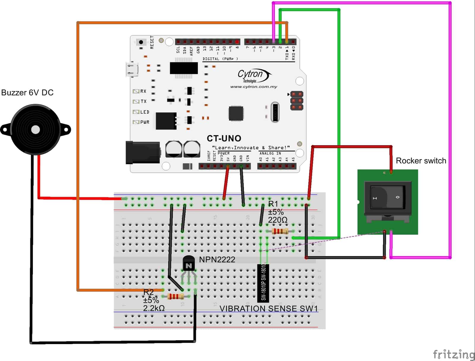
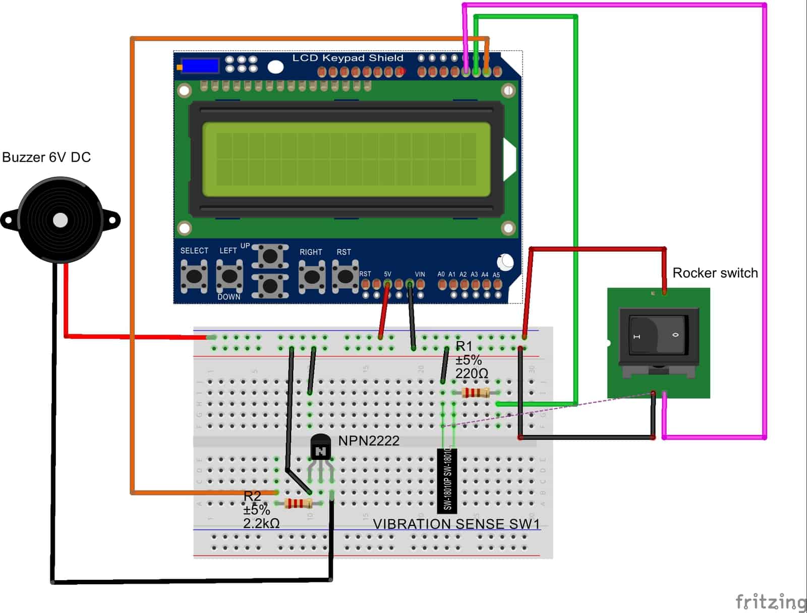
- Digital pin 1 is connected to the buzzer.
- Digital pin 2 is connected to the vibration sensor
- Digital pin 3 is connected to the switch.
- NPN2222 transistor is used to avoid current sinking from the buzzer to the CT-uno. You may refer to Part 1 for the explanation
- The 220-ohm resistor is attached to one end of the sensor and the CT-uno is used as a voltage divider to reduce the current flow.
- How to connect the vibration sensor SN-VBR-18010P?
- As you can see, one of the legs of the sensor is very thin and delicate. So, we must be extra gentle when dealing with it.
- To make it easy, I soldered both legs with a wire. If you are not familiar with soldering. Let me give you a quick tutorial:
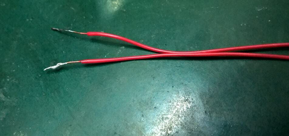
- Step 1: Cut 2 fair lengths of wires and strip the end.
- Step 2: Melt some solder lead onto each of the wire ends
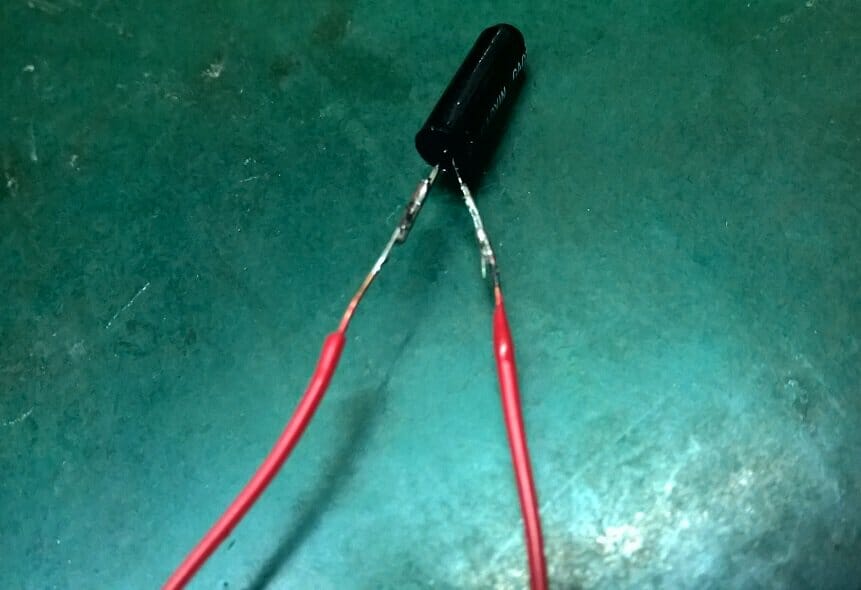
-
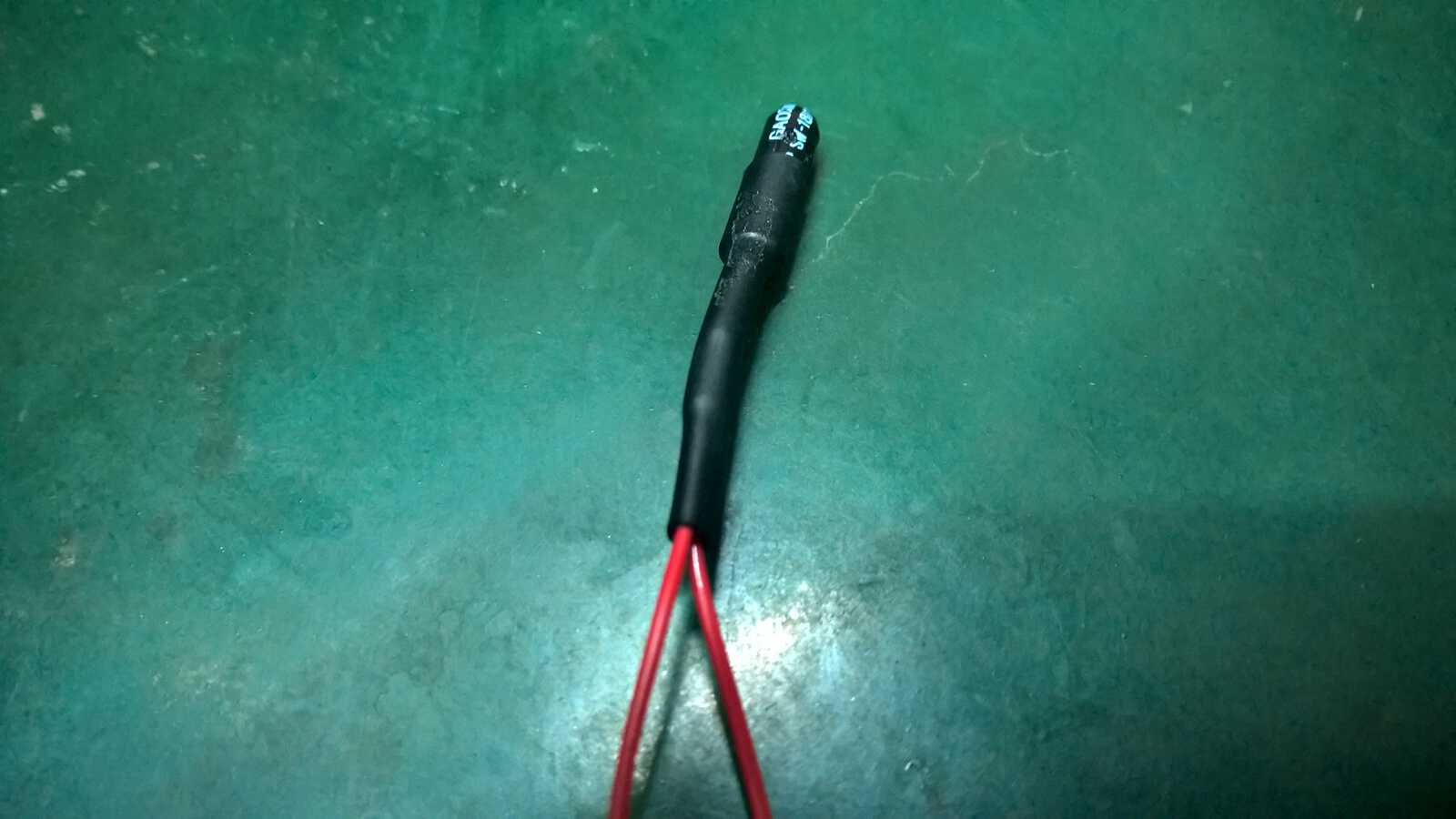
- Step 3: Melt some solder lead onto your solder bit. Then, place your soldered wire onto the leg of the sensor and solder them together. Do it for the other leg. Remember to be extra careful and gentle when dealing with the thinner leg. You should get this.
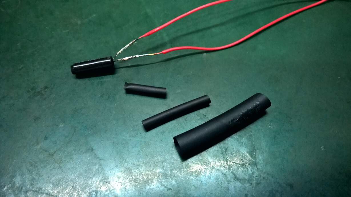
-

- Step 4: Now, because the thinner leg still looks very insecure, I am going to secure it with a heat shrink tube. I cut 2 small-size heat shrink tubes and one large-size heat shrink tube to protect the wires and secure the sensors' legs.
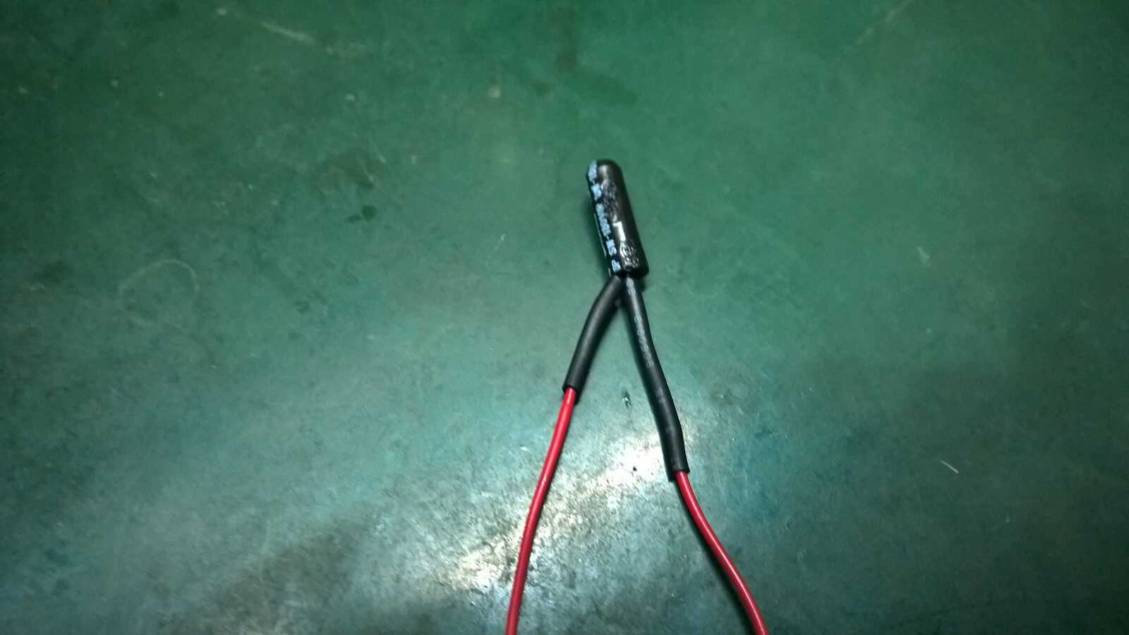
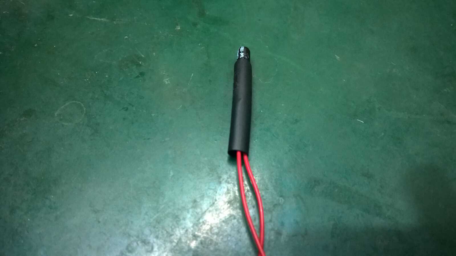
- Tada! Now your sensor is safe and sound! :D
Program
[code lang="c" highlight=""]
/*
The circuit:
* 16x2 character LCD to ARDUINO UNO
* LCD RS pin to digital pin 8
* LCD Enable pin to digital pin 9
* LCD D4 pin to digital pin 4
* LCD D5 pin to digital pin 5
* LCD D6 pin to digital pin 6
* LCD D7 pin to digital pin 7
* LCD R/W pin to ground
Tilt Sensor module to Arduino UNO
*VCC to 5V
*GND to GND
*Do to D2
*AO of tilt sensor is not used
*/
// include the library code:
#include
#include
#define Tilt 2 //Digital output from tilt sensor module is connected to D2
#define BUZZER 3 //LED at D3 pin
// initialize the library with the numbers of the interface pins
LiquidCrystal lcd(8, 9, 4, 5, 6, 7);
void setup() {
//setup the input or output pin
pinMode(BUZZER, OUTPUT);
pinMode(Tilt, INPUT);
digitalWrite(BUZZER, LOW); //off LED
// set up the LCD's number of columns and rows:
lcd.begin(16, 2);
// Print a message to the LCD.
lcd.print(" Lecture");
lcd.setCursor(0,1);
lcd.print(" Alarm");
delay(1000); //delay for 1 second
lcd.clear();
}
void loop() {
if(digitalRead(Tilt)) //if the DO from Tilt sensor is low, no tilt detected. You might need to adjust the potentiometer to get reading
{
digitalWrite(BUZZER,HIGH);
lcd.setCursor(0, 0); //move LCD cursor
lcd.print("SLEEPING"); //Display message
}
else
{
digitalWrite(BUZZER,LOW);
lcd.setCursor(0, 0); //move LCD cursor
lcd.print("AWAKE "); //Display message
}
}[/code]
LCD
You can also install an LCD to make it look more fun. I will be using an LCD Keypad Shield.
NOTE: LCD is using pin 4 to pin 9. Make sure that you do not use these pins for other purpose.
Set up
Program
[code lang="c" highlight=""]
//define library
#include
#include
//define pin name
#define vib_sensor 1
#define alarm 3
#define switch_button 2
int state = 0; //variable for reading the vibration sensor state
LiquidCrystal lcd(8, 9, 4, 5, 6, 7);
void setup() {
// put your setup code here, to run once:
pinMode(vib_sensor,INPUT); //initialize the vibration sensor as an input
pinMode(alarm,OUTPUT); //initialize the led sensor as an output
pinMode(switch_button,INPUT);
//set up the LCD's number of columns and rows:
lcd.begin(16,2);
lcd.print(" CYTRON ");
lcd.setCursor(0,1);
lcd.print(" ALARM ");
delay(2000);
}
void loop() {
// put your main code here, to run repeatedly:
//read the state of the vibration sensor value:
state = digitalRead(vib_sensor);
//check if there is vibration or not:
//if there is vibration, it will return a LOW state. If none, then it remain at HIGH state
while(digitalRead(switch_button)==HIGH){
if(state == LOW){
//LED remain off
digitalWrite(alarm, LOW);
lcd.setCursor(0,0);
lcd.print(" SAFE & SOUND ");
lcd.setCursor(0,1);
lcd.print(" ^__^ ");
}
else{
//LED turns on and off repeatedly
lcd.setCursor(0,0);
lcd.print(" INTRUDER ");
lcd.setCursor(0,1);
lcd.print(" ALERT!!! ");
digitalWrite(alarm,HIGH);
lcd.noDisplay();
delay(100);
digitalWrite(alarm,LOW);
lcd.display();
delay(100);
}
}
if (digitalRead(switch_button)==LOW){
lcd.setCursor(0,0);
lcd.print(" ALARM IS ");
lcd.setCursor(0,1);
lcd.print(" DISARMED ");
}
}
[/code]
That is all from me. I hope you had fun playing with your sensors! If you have anything to ask please go to our forum to post your question. Feel free to comment down below! Feedbacks are always welcome. :D
Source code:
1. Tilt Sensor Module --- Tilt_Module
2. Vibration Sensor --- vibration